Metabo KGS 303 Operations Instructions
Browse online or download Operations Instructions for Power tools Metabo KGS 303. Metabo KGS 303 Operating instructions User Manual
- Page / 60
- Table of contents
- BOOKMARKS
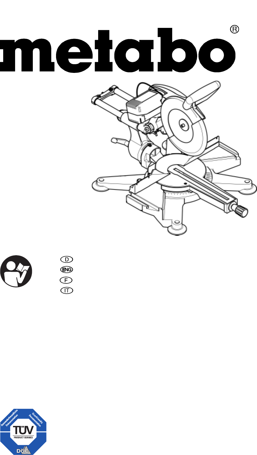
- KGS 303 Plus 1
- Volker Siegle 2
- ** 2006/42/EG, 2004/108/EG 2
- 3.3 Symbole auf dem Gerät 6
- 3.4 Sicherheitseinrichtungen 6
- 4. Aufstellung und Trans 6
- 5. Besondere Produkteigen 7
- 6. Das Gerät im Einzelnen 7
- 7.1 Anschluss einer Späne 8
- 7.2 Netzanschluss 8
- 7. Inbetriebnahme 8
- 8.1 Gerade Schnitte 9
- 8.2 Gehrungsschnitte 9
- 8. Bedienung 9
- 8.3 Geneigte Schnitte 10
- 8.4 Doppelgehrungsschnitte 10
- 8.5 Nutensägen 10
- 8.6 Zusatzanschlag 11
- 9. Wartung und Pflege 11
- 9.1 Sägeblatt wechseln 12
- 9.2 Antriebsriemen spannen 12
- 9.4 Justierungen 13
- 9.3 Tischeinlage wechseln 13
- 15. Technische Daten 15
- 15.1 Lieferbare Sägeblätter 16
- 3.3 Symbols on the machine 19
- 3.4 Safety devices 20
- 5. Special product features 21
- 6. Machine details 21
- 8.2 Mitre cuts 23
- 8.3 Bevel Cuts 23
- 8.4 Compound mitre cuts 24
- 8.5 Grooving 24
- 8.6 Auxiliary Fence 24
- 9.1 Changing the Saw Blade 25
- 9. Care and maintenance 25
- 9.2 Drive belt tensioning 26
- 9.3 Kerf plate replacement 26
- 9.4 Adjustments 26
- 13. Environmental Protection 28
- 14. Trouble Shooting 28
- 15. Technical specifications 28
- 15.1 Available saw blades 29
- FRANÇAIS 30
- ITALIANO 45
Summary of Contents
115 168 6660 / 0110 - 3.0KGS 303 PlusOriginalbetriebsanleitung. . . . . . . . . . . . . . .3Original operating instructions . . . . . . . . . .17Instr
10DEUTSCH2. Gewünschten Winkel einstellen. 3Hinweis: Der Drehtisch rastet in den Win-kelstufen 0°, 15°, 22,5°, 30°, 45° und 60° ein. 3. Feststellschr
11DEUTSCHplötzlich hochschlagen! Benutzen Sie beim Anfertigen von Nuten eine Spannvorrichtung. Vermeiden Sie seitlichen Druck auf den Sägekopf. Ausgan
12DEUTSCH9.1 Sägeblatt wechselnAGefahr! Kurz nach dem Sägen kann das Säge-blatt sehr heiß sein – Verbrennungs-gefahr! Lassen Sie ein heißes Säge-blatt
13DEUTSCH 2. Riemenspannung mit Daumen-druck prüfen. Wenn der Antriebsriemen nachge-spannt oder gewechselt werden muss: − Vier Schrauben der Motorbef
14DEUTSCH3Hinweis: Der Kipparm rastet in den Win-kelstufen 0°, 22,5° und 45° ein. 9.5 Gerät reinigenSägespäne und Staub mit Bürste oder Staubsauger e
15DEUTSCHMotor läuft nicht Keine Netzspannung: • Kabel, Stecker, Steckdose und Sicherung prüfen. Keine Kappfunktion Transport-Arretierung verriegelt:
16DEUTSCH15.1 Lieferbare Sägeblätter Absauganlage (nicht im Lieferumfang enthalten) − Anschlussdurchmesser Absaugstutzen − Mindest-Luftmengendurchsatz
17ENGLISH1. Components and Parts (standard delivery)12 4 56789101112131516171819222331420211 Handle 2 ON/OFF switch 3 Holder for Allen key 6 mm4 Motor
18ENGLISH1. Components and Parts (standard delivery) ...172. Please read first! ...183. Safety ...
19ENGLISH• Do not use the power cable for pur-poses it is not intended for. ARisk of injury by moving parts! • Do not operate the tool without install
D DEUTSCH ENG ENGLISHKONFORMITÄTSERKLÄRUNG DECLARATION OF CONFORMITYWir erklären in alleiniger Verantwortlichkeit, daß dieses Produkt mit den folge
20ENGLISHInformation on the nameplate: 3.4 Safety devicesRetractable blade guard The retractable blade guard (32) pro-tects against unintentional cont
21ENGLISH2. Lower the sawhead and push the transport locking pin (39) in. 3. Keep the packing for future use, or separate by material and dispose of i
22ENGLISHand swing the hinged fence to the rear. • Sawhead tilted between 22.5 ° and 48° to the left: swing the hinged fence up and tighten screw (47)
23ENGLISHCutting the work piece: 1. Hold workpiece against the fence. 2. Push the safety lock to the side and press and hold the ON/OFF switch. 3. Slo
24ENGLISH3. Tilt the motorhead slowly into the desired position. 3Note: The track arm holder engages at positive stops at the 0°, 22.5°, and 45° posi
25ENGLISH3. Loosen Phillips head screw (55) by one turn.4. Set auxiliary fence halves against the fence, for proper positioning guide the carriage bo
26ENGLISHADanger! Use only saw blades conforming to standards and which are designed for the maximum speed (see "Technical specifications")
27ENGLISH2. Loosen the two hexagon socket head cap screws (75) at the rear of the saw by approx. one turn. 3. Adjust the track arm holder until the sa
28ENGLISHThe machine's packing can be 100% recycled. Worn out power tools and accessories contain considerable amounts of valua-ble raw and rubbe
29ENGLISH15.1 Available saw blades Noise emission according to DIN EN 61029-1 **Sound power level LWA Sound pressure level at operator ear LPAdB (A)dB
3DEUTSCH1. Das Gerät im Überblick (Lieferumfang)12 4 56789101112131516171819222331420211 Handgriff 2 Ein-/Aus-Schalter 3 Werkzeugdepot für Innensechs-
30FRANÇAIS1. Vue générale de l'appareil (fourniture)12 4 56789101112131516171819222331420211 Poignée 2 Interrupteur « marche-arrêt » 3 Départemen
31FRANÇAIS1. Vue générale de l'appareil (fourniture) ...302. A lire impérativement !...313. Sécurité...
32FRANÇAISdre une position stable et à garder constamment votre équilibre. • N'utilisez pas l'appareil en pré-sence de liquides ou de gaz in
33FRANÇAISADanger dû à un défaut de l'appareil ! • Veuillez entretenir l'appareil et les accessoires avec soin. Respectez les instructions d
34FRANÇAIS AAttention ! Ne transportez pas l'appareil par la poignée vu qu'elle n'est pas conçue pour supporter le poids de l'appa
35FRANÇAISTable tournante Pour les coupes d'onglet, il est possi-ble de tourner la table tournante (42)d'environ 50° vers la gauche et de 60
36FRANÇAIS Le bras basculant se verrouille sur les niveaux d'angle 0°, 22,5° et 45°. AAttention ! Pour empêcher que l'angle d'incli-nai
37FRANÇAISnexion et de déconnexion puis maintenez-le appuyé. 3. Baissez lentement la tête de la scie. Lors du sciage, n'exercez pas une pression
38FRANÇAIS 3. Inclinez lentement le bras bascu-lant jusqu'à la position souhaitée. 3Remarque : Le bras basculant se verrouille sur les niveaux d
39FRANÇAIS8.6 Butée supplémentaire 3Remarque : Utilisez la butée supplémentaire pour les coupes droites de pièces plus hautes que la butée de l'a
4DEUTSCH1. Das Gerät im Überblick (Lieferumfang)...32. Zuerst lesen!...43. Sicherheit...
40FRANÇAIS5. Nettoyez les surfaces de serrage : − l'arbre de lame de scie, − la bride intérieure, − la lame de scie, − la bride extérieure, − la
41FRANÇAIS4. Placez une nouvelle pièce supplé-mentaire de la table puis ver-rouillez-la.5. Montez la butée de la pièce de tra-vail (69). 6. Rabattez l
42FRANÇAIS− Pour scier de longues pièces, utili-sez un appui approprié à gauche et à droite de la scie. − Lors des coupes obliques, mainte-nez la pièc
43FRANÇAIS15. Caractéristiques techniquesTension V 230 (1∼ 50 Hz)Courant consommé A 8,4 Protection par fusible A 10 (lent) Puissance du moteur* (p
44FRANÇAIS15.1 Lames de scie disponibles Diamètre Alésage Angle de tension Nombre de dents Utilisation N° d'art.250 mm 30 mm 5° nég. 24 dents à
45ITALIANO1. Visione d'insieme dell'apparecchio (ambito della fornitura)12 4 56789101112131516171819222331420211 Impugnatura 2 Interruttore
46ITALIANO1. Visione d'insieme dell'apparecchio (ambito della fornitura)...452. Istruzioni obbligatorie...463. Sicur
47ITALIANOseghe circolari e sono consapevoli, in qualsiasi momento, dei pericoli connessi all'utilizzo delle stesse. Le persone sotto i 18 anni d
48ITALIANO• I dispositivi di sicurezza o i compo-nenti danneggiati devono essere riparati, o eventualmente sostituiti, da tecnici specializzati e qual
49ITALIANOsul basamento della macchina, non è necessario montare i piedi in gomma. 2. Per il montaggio dei piedi in gomma è necessario rovesciare l&ap
5DEUTSCH• Halten Sie Unbeteiligte, insbeson-dere Kinder, aus dem Gefahrenbe-reich fern. Lassen Sie während des Betriebs andere Personen nicht das Gerä
50ITALIANO AAttenzione! Per fare in modo che l'angolo di smusso non venga modificato nelle operazioni di taglio, la vite di arresto del piano gir
51ITALIANO7.1 Collegamento di un impianto di aspirazione dei trucioli APericolo! Alcuni tipi di segatura (ad esempio quella ottenuta dal legno di quer
52ITALIANO Sezione massima del pezzo (dati in mm): Posizione di partenza − La sega è girata verso l'alto; − Delimitazione della profondità di ta
53ITALIANO5. Tagliare il pezzo da lavorare come descritto al punto "Tagli diritti". 8.4 Tagli ad angolo doppio 3Nota Il taglio ad angolo dop
54ITALIANOMontaggio della guida di battuta sup-plementare 1. Posizionare le rondelle sulle viti di chiusura (54) .2. Spingere le viti di chiusura (54)
55ITALIANOAPericolo! Non utilizzare detergenti che possano danneggiare le parti in alluminio (ad esempio per rimuovere resti di resina) riducendo così
56ITALIANO4. Inserire un nuovo profilo d'inserto facendolo scattare in posizione.5. Montare la battuta (69). 6. Sollevare la battuta ribaltabile
57ITALIANO− Non tagliare i pezzi di costa, ma sistemarli piatti sul piano girevole. − Tenere pulite le superfici dei tavoli di appoggio; in particolar
58ITALIANO15. Dati tecniciTensione V 230 (1∼ 50 Hz)Corrente assorbita A 8,4 Fusibile A 10 (inerte) Potenza del motore* (potenza nominale P1- S6 -
59ITALIANO15.1 Lame circolari disponibili Diametro Foro Angolo Numero denti Impiego N. d'ordine250 mm 30 mm 5° neg. 24 dente alternatoLegno, pan
6DEUTSCHAGefahr durch Lärm! • Tragen Sie einen Gehörschutz. • Achten Sie auch aus Lärmschutz-gründen darauf, dass das Sägeblatt nicht verzogen ist. Ei
60A 091 005 7561 B091 005 8010 C091 005 7553 D 091 005 7537 E091 005 7545 F091 005 8886 G 091 005 8827 H091 005 7529 I628 013 000 J 628 047 000
7DEUTSCH 7. Gerät auf eine geeignete Unterlage stellen:− Alle vier Füße des Gerätes müs-sen fest auf der Unterlage ste-hen. − Die ideale Höhe der Unte
8DEUTSCH Wenn die Zugvorrichtung nicht benötigt wird, Zugvorrichtung mit der Feststell-schraube (44) arretieren. Schnitttiefenbegrenzung Die Schnittti
9DEUTSCH• Schützen Sie das Netzkabel vor Hitze, aggressiven Flüssigkeiten und scharfen Kanten. • Verwenden Sie als Verlänge-rungskabel nur Gummikabel
Related products and manuals for Power tools Metabo KGS 303


 (48 pages)

 (108 pages)
 (15 pages)
© 2020, manymanuals.com. All rights reserved. | 1.371 s |
 Manymanuals.com
 Manymanuals.de
 Manymanuals.fr
 Manymanuals.it
 Manymanuals.pl
 Manymanuals.cz
 Manymanuals.es
 Manymanuals-pt.com
Comments to this Manuals