Metabo Welding Machine MIG/MAG 160 Specifications Page 16
- Page / 52
- Table of contents
- BOOKMARKS
- MIG MAG 150/20 XT 1
- MIG MAG 170/30 XTC 1
- MIG MAG 200/40 XT 1
- MIG MAG 250/60 XT 1
- MIG MAG 300/45 XT 1
- Schweißgerät MIG MAG 2
- 2.1 Bestimmungsgemäße 3
- Verwendung 3
- Inhaltsverzeichnis 3
- 1. Zuerst lesen! 3
- 2. Sicherheit 3
- 2.2 Symbole auf dem Gerät 4
- 3.1 Bedienteil 4
- 3. Bedienelemente 4
- (34) gegen Umfallen sichern 6
- 6. Bedienung 7
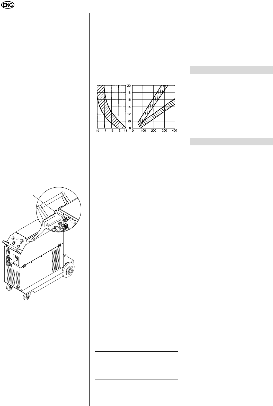
- Schutzgasmenge in l/min 8
- Aluminium Stahl 8
- Stromstärke in A 8
- Gasdüsendurchmesser 8
- 11.1 Allgemeine Störungen 9
- 8. Lieferbares Zubehör 9
- 9. Reparatur 9
- 10. Umweltschutz 9
- 11. Störungen 9
- 12. Technische Daten 10
- 2. Safety 11
- 2.1 Specified Conditions of 11
- Table of Contents 11
- 1. Please Read First! 11
- 2.2 Symbols Used 12
- 3.1 Control Panel 12
- 3.2 MIG/MAG 150/20 XT 12
- 3.3 MIG/MAG 170/30 XTC 12
- 3. Operating Elements 12
- 6.1 LED Indicators 15
- 6.2 Setting the Welding 15
- Parameters 15
- 6. Operation 15
- Current in A 16
- Gas shroud diameter 16
- 11.1 Trouble Shooting 17
- 9. Repairs 17
- 10. Environmental Protection 17
- 11. Faults 17
- 12. Technical Specifications 18
- FRANÇAIS 19
- NEDERLANDS 27
- Indice del contenido 35
- 2. Seguridad 35
- 2.1 Uso según su finalidad 36
- 2.2 Símbolos en la máquina 36
- 3.1 Elemento de mando 36
- 3. Elementos de mando 36
- 3.4 MIG/MAG 200/40 XT 37
- MIG/MAG 250/60 XT y 37
- MIG/MAG 300/45 XT 37
- 4. Transporte 37
- 5.4 Introducción del alambre 39
- 11.1 Averías generales 42
- 11. Averías 42
- 12. Especificaciones técnicas 42
- 2.1 Korrekt anvendelse 44
- Indholdsfortegnelse 44
- 1. Læses først! 44
- 2. Sikkerhed 44
- 2.2 Symboler på apparatet 45
- 3.1 Betjeningsdel 45
- 3. Betjeningselementer 45
- MIG/MAG 250/60 XT og 46
- 4.1 Krantransport 46
- 4. Transport 46
- 5.1 Tilslut gasflasken 47
- 5.2 Strømtilslutning 47
- 5.3 Sæt svejsetrådrullen i 47
- 5.4 Før svejsetråden ind 47
- 5. Driftsforberedelse 47
- 6. Betjening 48
- Beskyttelsesgasmængde i l/min 49
- Aluminium Stål 49
- Strømstyrke i A 49
- Gasdysediameter 49
- 11.1 Generelle forstyrrelser 50
- 9. Reparation 50
- 10. Miljøbeskyttelse 50
- 11. Forstyrrelser 50
- 12. Tekniske Data 51
Related products and manuals for Welding System Metabo Welding Machine MIG/MAG 160
 (52 pages)

 (17 pages)
© 2020, manymanuals.com. All rights reserved. | 2.306 s |
 Manymanuals.com
 Manymanuals.de
 Manymanuals.fr
 Manymanuals.it
 Manymanuals.pl
 Manymanuals.cz
 Manymanuals.es
 Manymanuals-pt.com
Comments to this Manuals